The Facts About Wedge Barriers Revealed
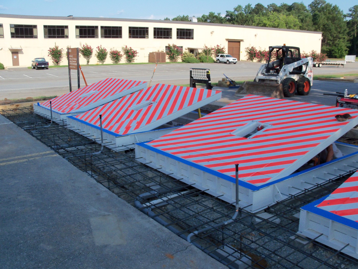
In the complying with conversation, recommendation is made to a surface area of a foundation to which the wedge-style barrier is placed. In the detailed embodiments, the top side of the anchor is significantly flush with the surface of the foundation. In such personifications, the wedge-style barrier might be installed straight to the surface of the foundation. In other personifications, the top side of the anchor might be slightly increased above the surface area of the structure or somewhat recessed listed below the surface area of the structure. 1 is a front viewpoint sight of an embodiment of a surface-mounted wedge-style obstacle 10. As shown, the obstacle 10 is installed to a surface 12 of a foundation 14(e. g., a superficial structure ). For example, the foundation
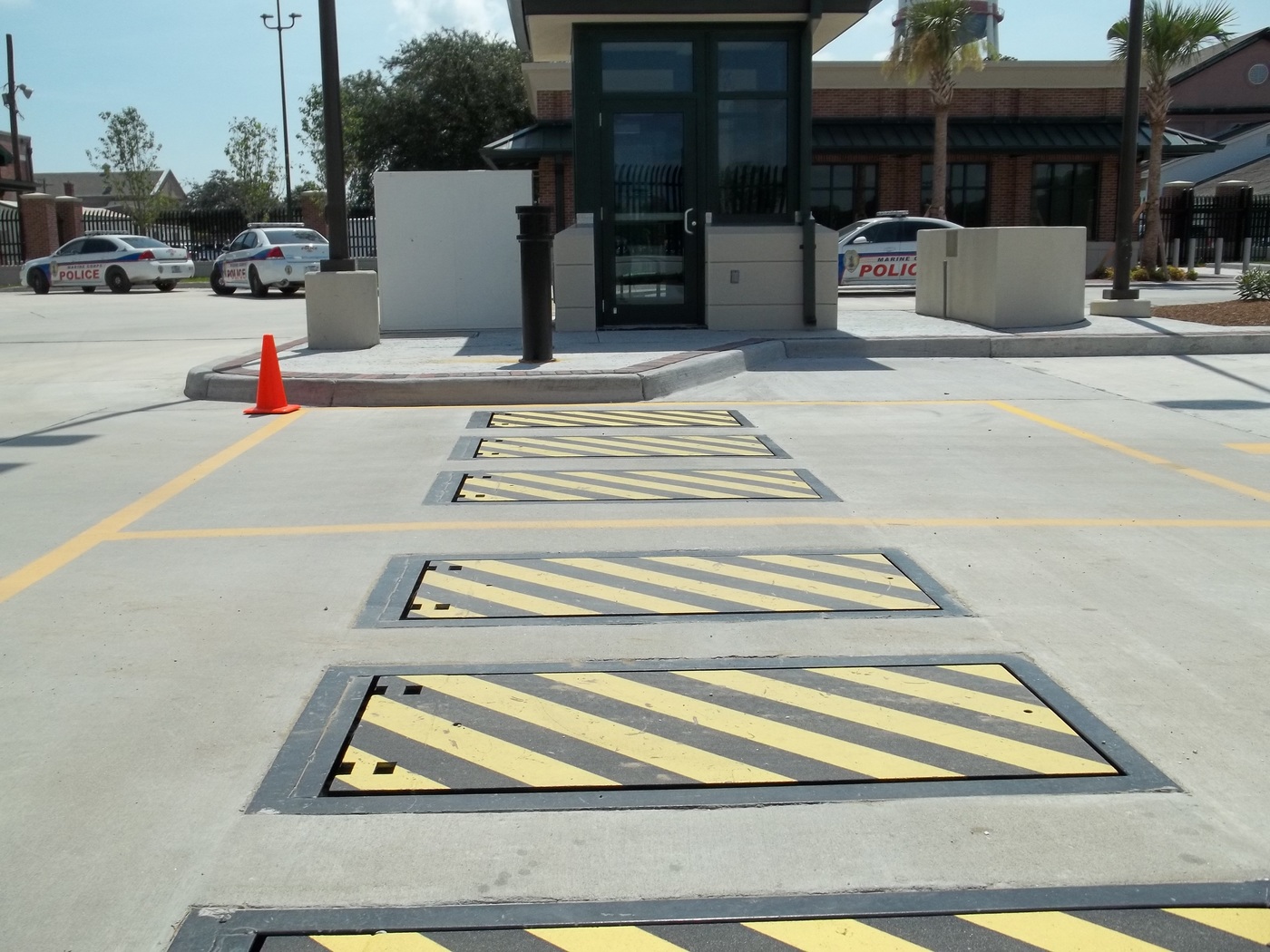
14 and the surface area 12 to which the obstacle 10 is safeguarded might be made from concrete - Wedge Barriers. 2, the obstacle 10 is placed to or includes a support or subframe (e. g., support 30 displayed in FIG. 2 )secured below the surface 12. For instance, the bather 10 may be bolted to the anchor or safeguarded to the support by other mechanical bolts. In the illustrated embodiment, the obstacle 10 includes a wedge plate 16, which consists of a part that is substantially identical with the surface 12 when the obstacle 10 is in the pulled back placement. Simply put, lorries or individuals might overlook the barrier 10 when the obstacle 10 remains in the retracted setting and experience minor altitude loved one to the surface 12 while on the barrier 10. As gone over thoroughly below, when the barrier 10 remains in the released placement, the wedge plate 16 is held and sustained in an elevated position by a lifting system of the barrier 10. In addition, the components 18 may be bolted or otherwise mechanically coupled to one an additional. In this fashion, repair service or replacement of one or even more elements 18 might be streamlined and streamlined. That is, repair service or substitute of single components
18 might be done more quickly, quickly, and price successfully. FIG. In certain embodiments, the support 30 might be a steel structure consisting of plates, beam of lights(e. g., I-beams ), and/or other structures that are protected within the structure 14, which might be concrete. At the surface 12, an upper side 28 of the anchor 30 may be at the very least partly revealed
, therefore enabling the accessory of the obstacle 10 to the support 30. g., threaded holes)in one or even more beam of lights or plates of the anchor 30 might be exposed to the surface area 12. In this fashion, screws 32 or other mechanical bolts might be used to secure the obstacle 10 to the support 30. As the obstacle 10 is mounted to the surface area 12 of the foundation 14, collection of debris and other product beneath the obstacle might be reduced, and components of the bather 10 may not be revealed to below quality settings. As suggested by reference character 52, the lifting system 50 consists of components disposed underneath the wedge plate 16. For example, the parts 52 beneath the wedge plate 16 may consist of an electromechanical actuator, a web cam, one or more webcam surface areas, etc. In addition, the training system 50 includes a springtime setting up 54
The spring pole 58 is combined to a web cam(e. g., camera 80 received FIG. 4) of the training device 50. The springs More Info 60 disposed regarding the springtime rod 58 are held in compression by springtime supports 62, consisting of a repaired springtime support 64. That is, the set spring support 64 is repaired about the structure 14 and the rest of the bather 10.
How Wedge Barriers can Save You Time, Stress, and Money.
g., spring support 65 Recommended Reading )may be fixed to the end of the springtime pole 58 to enable compression of the springs 60. As the springtimes 60 are compressed in between the springtime sustains 62, the springtime setting up 54 creates a pressure acting on the web cam paired to the spring pole 58 in an instructions 66. For example, the staying pressure put on
the web cam to release the wedge plate 16 may be provided by an electromechanical actuator 84 or other actuator. The springtime assembly 54 and the actuator 84(e. g., electromechanical actuator)may operate with each other to convert the cam and raise the wedge plate 16.
As pointed out above, the springtime setting up 54 exerts a constant pressure on the cam, while the electromechanical actuator may be regulated to apply a variable pressure on the webcam, thus making it possible for the training and decreasing( i. e., releasing and pulling back )of the wedge plate 16. In certain personifications, the consistent force used by the springtime assembly 54 may be flexible. g., electromechanical actuator) is impaired. As will certainly be appreciated, the spring setting up 54 may be covered and protected from debris or various other components by a cover plate(e. g., cover plate 68 received FIG. 4) that may be considerably flush with the raised surface 38 of the foundation 14. As mentioned above, in the released position, the wedge plate 16 serves to block accessibility or traveling beyond the barrier 10. For example, the barrier 10(e. g., the wedge plate 16 )might obstruct pedestrians or lorries from accessing a property or path. As talked about over, the obstacle 10 is connected to the support 30 secured within the foundation 14,
front brackets 71. Therefore, the affiliation settings up 72 might pivot and revolve to allow the collapse and extension of the affiliation assemblies 72 during retraction and release of the bather 10. The linkage assemblies 72 reason activity of the wedge plate 16 to be limited. If a car is traveling in the direction of the released wedge plate 16(e. For example, in one situation, the security legs 86 might be expanded throughoutmaintenance of the barrier 10. When the safety legs 86 are deployed, the safety and security legs 86 sustain the weight of the wedge plate 16 versus the surface area 12. As an outcome, the lifting system 50 may be deactivated, serviced, eliminated, changed, etc. FIG. 5 is partial perspective view of an embodiment of the surface-mounted wedge-style obstacle 10, illustrating the webcam 80 and the web cam surfaces 82 of the lifting system 50. Particularly, 2 camera surfaces 82, which are described as lower webcam surfaces 83, are positioned below the cam 80. The reduced web cam surface areas 83 might be repaired to the surface area 12 (e. For example, the lower camera surfaces 83 and the mounting plate 85 may create a solitary piece that is secured to the support 30 by bolts or various other mechanical fasteners. Furthermore, 2 web cam surface areas 82, which are described as upper web cam surface areas 87, are positioned over the webcam 80 and coupled to (e. In other embodiments, stepping in layers or plates might be placed in between the surface area 12 and the reduced cam surface areas 83 and/or the wedge plate 16 and the upper web cam surface areas 87 As stated above, the webcam
80 equates along the cam surface areas 82 when the wedge plate 16 is raised from the pulled back placement to the released position. Additionally, as stated above, the spring assembly 54 (see FIG. 3 )may provide a force acting upon the camera 80 in the direction 102 by means of spring rod 58, which might reduce the pressure the electromechanical actuator 84 is required to relate to the camera 80 in order to activate and raise the wedge plate 16. 1 )to the released setting(see FIG. 4). As revealed, the webcam 80 includes track wheels 104(e. g., rollers), which contact and convert along the webcam surfaces 82 throughout procedure.